Hello Friends,
I am cyberautics and in this session we learn about the How to interface current sensor and How to work with Current sensor(ACS712), In the earlier session we learn about the interfacing of voltage Sensor if you still not read that blog than click here.
I am cyberautics and in this session we learn about the How to interface current sensor and How to work with Current sensor(ACS712), In the earlier session we learn about the interfacing of voltage Sensor if you still not read that blog than click here.
BASICS OF CURRENT SENSOR(ACS712)- If you recall the previous Arduino project, We have discussed about measuring voltage with Arduino using a Voltage Sensor. In this project, we will learn about measuring current using a Current Sensor (ACS712).
- A Current Sensor is an important device in power calculation and management applications. It measures the current through a device or a circuit and generates an appropriate signal that is proportional to current measured. Usually, the output signal is an analog voltage.
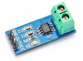
- The ACS712 Current Sensor is a product of Allegro MicroSystems that can be used for precise measurement of both AC and DC currents. This sensor is based on Hall Effect and the IC has an integrated Hall Effect device.
- Coming to the output of the ACS712 Current Sensor, it produces an analog voltage that is proportional to AC or DC currents (whichever is being sensed).
- Pin connections :

1 & 2 IP+ : +ve terminals for sensing current3 & 4 IP-: -ve terminals for sensing current5 GND : ground the signals6 FILTER : External Capacitor (to set the bandwidth)7 VIOUT : Analog Output8 VCC : Power Supply
Components
- Arduino UNO
- ASC712 Current Sensor Module
- Resistor (220 ohm)
- Power supply
- PCB/Breadboard
- Connecting wires
CIRCUIT DIAGRAM

Make a connection as per the Diagram
CODE
const int currentPin = A0; //declare analog input pinint sensitivity = 66; //declare + initialization of variableint adcValue= 0; //make a variable names adcvalueint offsetVoltage = 2500; //declare + initialization of variabledouble adcVoltage = 0; //declare + initialization of variabledouble currentValue = 0; //declare + initialization of variable
void setup() { Serial.begin(9600); }void loop(){ //calculaton start adcValue = analogRead(currentPin); adcVoltage = (adcValue / 1024.0) * 5000; currentValue = ((adcVoltage - offsetVoltage) / sensitivity); // calculation end delay(2000); Serial.print("\t Current = "); Serial.println(currentValue); }
EXPLANATIONMake the connections and upload the code to Arduino. In the code, there is a small calculation for measuring the current.
- ACS712 can be used for measuring either AC or DC currents, Arduino can be implemented to measure the same
The ASC712 is based on Hall Effect. There is a copper strip connecting the IP+ and IP- pins internally. When some current flows through this copper conductor, a magnetic field is generated which is sensed by the Hall Effect sensor. The Hall Effect sensor then converts this magnetic field into appropriate current. In this method, the input and the output are completely isolated.
So, my dear friends I hope this blog is very useful for you if you have any doubts or any questions you can directly contact me.
- If you recall the previous Arduino project, We have discussed about measuring voltage with Arduino using a Voltage Sensor. In this project, we will learn about measuring current using a Current Sensor (ACS712).

- A Current Sensor is an important device in power calculation and management applications. It measures the current through a device or a circuit and generates an appropriate signal that is proportional to current measured. Usually, the output signal is an analog voltage.
- The ACS712 Current Sensor is a product of Allegro MicroSystems that can be used for precise measurement of both AC and DC currents. This sensor is based on Hall Effect and the IC has an integrated Hall Effect device.
- Coming to the output of the ACS712 Current Sensor, it produces an analog voltage that is proportional to AC or DC currents (whichever is being sensed).
- Pin connections :

1 & 2 IP+ : +ve terminals for sensing current
3 & 4 IP-: -ve terminals for sensing current
5 GND : ground the signals
6 FILTER : External Capacitor (to set the bandwidth)
7 VIOUT : Analog Output
8 VCC : Power Supply
Components
- Arduino UNO
- ASC712 Current Sensor Module
- Resistor (220 ohm)
- Power supply
- PCB/Breadboard
- Connecting wires
CIRCUIT DIAGRAM

Make a connection as per the Diagram
CODE
const int currentPin = A0; //declare analog input pin
int sensitivity = 66; //declare + initialization of variable
int adcValue= 0; //make a variable names adcvalue
int offsetVoltage = 2500; //declare + initialization of variable
double adcVoltage = 0; //declare + initialization of variable
double currentValue = 0; //declare + initialization of variable
void setup()
{
Serial.begin(9600);
}
void loop()
{
//calculaton start
adcValue = analogRead(currentPin);
adcVoltage = (adcValue / 1024.0) * 5000;
currentValue = ((adcVoltage - offsetVoltage) / sensitivity);
// calculation end
delay(2000);
Serial.print("\t Current = ");
Serial.println(currentValue);
}
EXPLANATIONMake the connections and upload the code to Arduino. In the code, there is a small calculation for measuring the current.
- ACS712 can be used for measuring either AC or DC currents, Arduino can be implemented to measure the same
The ASC712 is based on Hall Effect. There is a copper strip connecting the IP+ and IP- pins internally. When some current flows through this copper conductor, a magnetic field is generated which is sensed by the Hall Effect sensor. The Hall Effect sensor then converts this magnetic field into appropriate current. In this method, the input and the output are completely isolated.
So, my dear friends I hope this blog is very useful for you if you have any doubts or any questions you can directly contact me.
- Make the connections and upload the code to Arduino. In the code, there is a small calculation for measuring the current.
- ACS712 can be used for measuring either AC or DC currents, Arduino can be implemented to measure the same
- The ASC712 is based on Hall Effect. There is a copper strip connecting the IP+ and IP- pins internally. When some current flows through this copper conductor, a magnetic field is generated which is sensed by the Hall Effect sensor. The Hall Effect sensor then converts this magnetic field into appropriate current. In this method, the input and the output are completely isolated.
Cool
ReplyDeleteThis comment has been removed by the author.
DeleteIt's ossum
ReplyDelete