Hello Friends,
BASIC
Vcc : Power to LCD module (+5V supply is given to this pin)
VEE : Contrast adjustment pin. This is done by connecting the ends of a 10K potentimeter to +5V and ground and then connecting the slider pin to the VEE pin. The voltage at the VEE pin defines the contrast. The normal setting is between 0.4 and 0.9V.
RS : Register select pin.
R/W : Read/Write modes. This pin is used for selecting between read and write modes. Logic HIGH at this pin activates read mode and logic LOW at this pin activates write mode.
EN : This pin is meant for enabling the LCD module. A HIGH to LOW signal at this pin will enable the module.
DB0 to DB7 : These are data pins. The commands and data are fed to the LCD module though these pins.
LED+: Anode of the back light LED. When operated on 5V, a 560 ohm resistor should be connected in series to this pin. In arduino based projects the back light LED can be powered from the 3.3V source on the arduino board.
LED- : Cathode of the back light LED.
I am cyberautics today we will learn about how to interface LCD Display with arduibo and how to work with LCD display , we mainly prefer serial monitor for checking output same task we will perform using LCD Dislplay ,We can monitor the output data on LCD Display.
If you still not read previous blog please click here.
BASIC- A Liquid Crystal Display commonly abbreviated as LCD is basically a display unit built using Liquid Crystal technology.
- When we build real life/real world electronics based projects, we need a medium/device to display output values and messages.
- For this requirement is best available option is Liquid Crystal Displays which comes in different size specifications. Out of all available LCD modules in market, the most commonly used one is 16×2 LCD Module which can display 32 ASCII characters in 2 lines (16 characters in 1 line).
- 16x2 = 16 columns x 2 Rows.
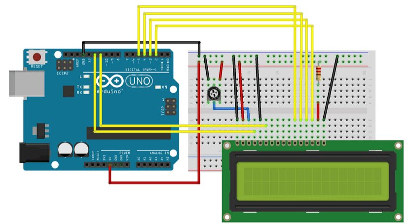
PIN DIAGRAM AND CIRCUIT DIAGRAM

- A Liquid Crystal Display commonly abbreviated as LCD is basically a display unit built using Liquid Crystal technology.
- When we build real life/real world electronics based projects, we need a medium/device to display output values and messages.
- For this requirement is best available option is Liquid Crystal Displays which comes in different size specifications. Out of all available LCD modules in market, the most commonly used one is 16×2 LCD Module which can display 32 ASCII characters in 2 lines (16 characters in 1 line).
- 16x2 = 16 columns x 2 Rows.
PIN DIAGRAM AND CIRCUIT DIAGRAM

GND : Ground pin of the LCD module.
Vcc : Power to LCD module (+5V supply is given to this pin)
VEE : Contrast adjustment pin. This is done by connecting the ends of a 10K potentimeter to +5V and ground and then connecting the slider pin to the VEE pin. The voltage at the VEE pin defines the contrast. The normal setting is between 0.4 and 0.9V.
RS : Register select pin.
R/W : Read/Write modes. This pin is used for selecting between read and write modes. Logic HIGH at this pin activates read mode and logic LOW at this pin activates write mode.
EN : This pin is meant for enabling the LCD module. A HIGH to LOW signal at this pin will enable the module.
DB0 to DB7 : These are data pins. The commands and data are fed to the LCD module though these pins.
LED+: Anode of the back light LED. When operated on 5V, a 560 ohm resistor should be connected in series to this pin. In arduino based projects the back light LED can be powered from the 3.3V source on the arduino board.
LED- : Cathode of the back light LED.
 make a connection as per diagram.
 CODE
#include<LiquidCrystal.h> //fetch inbuilt library
CODE
#include<LiquidCrystal.h> //fetch inbuilt library
LiquidCrystal lcd(12, 11, 5, 4, 3, 2); // sets the interfacing pinsvoid setup(){ lcd.begin(16, 2); // initializes the 16x2 LCD}void loop(){ lcd.setCursor(0,0); //sets the cursor at row 0 column 0 lcd.print("16x2 LCD MODULE"); // prints 16x2 LCD MODULE lcd.setCursor(2,1); //sets the cursor at row 1 column 2 lcd.print("HELLO WORLD"); // prints HELLO WORLD}EXPLANATION
- For establish communication between Arduino and LCD module, we make use of a built in library in Arduino <LiquidCrystal.h> – which is written for LCD modules making use of the Hitachi HD44780 chipset (or a compatible chipset).
- Library “LiquidCrystal.h” is used for easily controlling the LCD module using Arduino board with the help of built in methods defined inside the library .
- For example, data string can be printed on the LCD module by merely calling a method lcd.print(). If you want to print “Hello World”.
- At row 1, starting from column 3; first set the cursor at the desired position using method lcd.setCursor(1,3) and then write the command to print the characters as lcd.print(“Hello World”); .
- The LiquidCrystal.h library provides functions/methods for almost all applications like printing a string, setting the cursor, initializing the LCD, scrolling the display, auto scroll, clear LCD, blink cursor etc.
- LiquidCrystal lcd() – is a constructor used to declare a variable of its type. Here ‘lcd’ is the variable declared using the constructor and is used to invoke methods defined inside the library LiquidCrystal.h (Example – lcd.print(); lcd.setCursor() and other methods)
- lcd.begin() – is called to initialize the lcd screen and to pass the dimension of lcd screen (columns, rows) as parameters of the invoked method.
So, My dear friends I hope this session is very useful for you , if you have any question or any doubts you can directly contact me.
LiquidCrystal lcd(12, 11, 5, 4, 3, 2); // sets the interfacing pins
void setup()
{
lcd.begin(16, 2); // initializes the 16x2 LCD
}
void loop()
{
lcd.setCursor(0,0); //sets the cursor at row 0 column 0
lcd.print("16x2 LCD MODULE"); // prints 16x2 LCD MODULE
lcd.setCursor(2,1); //sets the cursor at row 1 column 2
lcd.print("HELLO WORLD"); // prints HELLO WORLD
}
EXPLANATION
- For establish communication between Arduino and LCD module, we make use of a built in library in Arduino <LiquidCrystal.h> – which is written for LCD modules making use of the Hitachi HD44780 chipset (or a compatible chipset).
- Library “LiquidCrystal.h” is used for easily controlling the LCD module using Arduino board with the help of built in methods defined inside the library .
- For example, data string can be printed on the LCD module by merely calling a method lcd.print(). If you want to print “Hello World”.
- At row 1, starting from column 3; first set the cursor at the desired position using method lcd.setCursor(1,3) and then write the command to print the characters as lcd.print(“Hello World”); .
- The LiquidCrystal.h library provides functions/methods for almost all applications like printing a string, setting the cursor, initializing the LCD, scrolling the display, auto scroll, clear LCD, blink cursor etc.
- LiquidCrystal lcd() – is a constructor used to declare a variable of its type. Here ‘lcd’ is the variable declared using the constructor and is used to invoke methods defined inside the library LiquidCrystal.h (Example – lcd.print(); lcd.setCursor() and other methods)
- lcd.begin() – is called to initialize the lcd screen and to pass the dimension of lcd screen (columns, rows) as parameters of the invoked method.
So, My dear friends I hope this session is very useful for you , if you have any question or any doubts you can directly contact me.
Ossum & helpful
ReplyDeleteUseful
ReplyDelete